LTCC Green Tape Laser Punching System
|
ProVia GT Brochure
LTCC Green Tape, Laser Punching(Drilling) System | ||||||||||||||||||||||||||||||||||||||||||||||||||||||||||||||||||||||
|
Based on the rugged Dual Scan Head and workstation utilizes a production-proven RF-CO2 laser for optimized machining in all common Green Tape materials.
Lasers have been used to process Green Tape Punching for Micro Via Hole Drilling below 90um. The current requirements for precision processing of parts for the hard disk drive industry and the electronics packaging industry (multi-chip modules) are typical of the applications where lasers provide manufacturers with significant advantages. The ProVia GT is the ultimate processing workstation for LTCC Green Tape, with high performance galvos for rapid point-to-point drilling and routing complex features. The CO2 laser is appropriate for high speed machining (drilling, cutting and skiving) of Green Sheet.
Consult the LTCC processing applications note for more information.
Specifications*
|

ProVia-GT 프리젠테이션 File에 대하여 질문과 답변 입니다
There had questions in the ProVia-GT presentation file as below
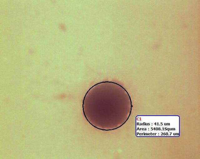
직경 83um Connection Single Via-Hole at Exit Face
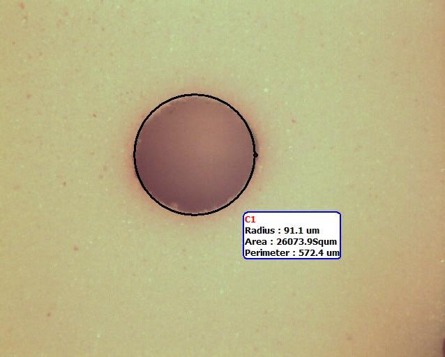
직경182.2um Thermal Via-Hole at Exit Face
1) 위 사진에는 출사면 쪽의 반경 41.5um와 91.1um의 비아홀만 보인다. 그린 테이프의 두께와 경사각도에 대하여 절단면 사진으로 알려 주시오.
There had only exit face of holes as shown a radius 41.5um. The green tape thickness and tape ratio is not described. Could you let me know with cross section pictures?
[경사각도는 더 많은 Shot이나 혹은 높은 에너지 밀도로 감소된다. 즉, Hole의 경사각을 Straight로 하려면 그만큼 Drilling 속도가 늦어지고, 에너지 밀도를 올리면 큰 비아홀 Shot Drill하는 능력이 제한된다.
The taper can be reduced (i.e. straighter sidewalls) by using more pulses (which means a slower drilling process), or higher energy density (which limits the ability to drill larger holes).
절단면을 찍은 사진이 없으므로, Drilling을 하였던 사례로 설명한다. 고객의 요구 사양은 100um두께의 재질에 80um via Hole 이었다. PPI에서는 Single Laser Pulse로 입사면에서 100um ~ 105um, 출사면에서는 75um ~ 80um의 Via Holes을 Drill 하였다. 경사각도는 Pulse Length에 수반되는 Pulse의 Peak Power에 의하여 변동이 있다. 이 Via Holes은 Mylar층을 첫 번째 관통하여 Drill하였고, 입사면 쪽은 Ceramic/Mylar 접합 면에서 측정한 것이다.
We do not have the capability to cross-section the vias, and no customer has given us a photo. However, as an example, one customer was asking for 80um diameter holes in 100um thick material. We were able to make entrance holes about 100-105um diameter and exit holes 75-80um diameter with a single laser pulse. Taper can be varied by the peak power of the pulse, as well as the pulse length. These holes were drilled through the mylar first, and the entrance hole measured at the Ceramic/Mylar interface.
Taper는 2- Shot을 사용하면 감소된다. Via Holes에 가해지는 전체 Laser Energy에 의존하여, 입사면의 동일 Hole Size (100um~105um)에 대하여 출사면은 85um ~ 95um로 Drill 된다.
By using a two-pulse process, the taper would also be reduced. For the same size of entrance holes (100-105um), the exit holes would be 85-95um, depending on the total laser energy delivered to the via-hole. ]
2) ProVia_GT에서 비아홀의 직경은 어떻게 변경하는가?
How can ProVia-GT changes to via holes diameters? Ex) select by turret lens or fixed beam spot size + trepanning
[간단한 구조의 공압 셔틀이 2개의 고정된 홀 크기의 광학계를 움직여 홀 크기를 설정한다. 더 큰 홀들은 Trepanning을 설정하여 가공한다. Trepanning속도는 펄스로 한 점을 드릴 하는 것에 비하여 훨씬 느리다.
A simple pneumatic shuttle will allow changing between two fixed sizes by moving additional optics into the main beam. Any larger sized hole can also be created by trepanning as you have said. Trepanning will be a slower process than point drilling with one or several pulses.]
3) 그린테이프는 기계적인 펀칭으로 가이드 홀을 만들고, 그 다음 공정인 드릴에서는 가이드 홀을 비전으로 인식하여 그 기준으로 비아홀을 Drill한다. 왜냐하면 가이드 홀의 가공은 레이저드릴이 펀칭보다 거칠기 때문이다. 실제로 ProVia-GT의 고객 쪽에서 이런 문제가 있었는가? 만일, 레이저드릴의 가공 홀이 깨끗하다면, 2단계의 번거로운 공정이 필요 없으니 강점이 될 것이다.
The green tape had guide holes by punching machine, and then driller referenced by these holes position as vision recognize. Because of, Laser drilled guide hole’s edge quality is lower then punching holes. Actually, Is the ProVia-GT having this problem at other customers? If an edge quality is a good condition, it may be our advantage to drilling via hole and guide holes at once without 2-steps.
[펀칭은 깨끗하게 가공을 하지만, ProVia-GT의 고객들은 가이드 홀 가공을 레이저 드릴에서 Trepanning방법으로 작업한다. 홀의 깨끗함은 충분하기 때문이다. 거기에는 확실히 레이저로 가이드 홀을 가공하는 강점이 있다: 툴링홀로부터 비아홀까지의 레지스트레이션 정밀도는 훨씬 좋다. 그리고 그린테이프는 한 기계에서 한번에 처리되므로 장점이 된다.
Punching will give a very clean edge, but our customer does use trepanning for the tooling (guide) holes, so the edge quality is good enough for them. There is certainly an advantage to laser drill the guide holes: the registration accuracy from tooling holes to vias is quite good; and the tapes only need to be handled once, on one machine.]
4) 분진을 빨아들이는 능력이 좋다고 하더라도 비아홀 주변에는 분진이 남아 있다. 그래서 장비에 클리닝 롤러를 설치한다. ProVia-GT에서 설치할 수 있는가? 혹은 드릴 후에 깨끗하게 할 수 있는 방법이 있는가? 여기에 대하여 알고 있는가?
The suction is a good, but debris still remained near by via holes, so that their installed system had a cleaning roller. Can we provide it? Or can we keep clean status after drilling? Did you heard about that?
[표면의 분진은 흰색 위에 흰색으로 남아있기 때문에 육안으로 보기가 어렵지만, 거기에는 항상 분진이 있기 마련이다. 고객이 장비사양으로 클리닝 롤러를 설치하기를 원한다면 언로더에서 자동화의 한 부분으로 설치할 수 있다. 비아홀 내의 분진을 제거하기 위하여 Air Knife의 설치를 제안 했었다. 홀 내벽의 분진은 표면 분진보다 더 큰 문제일 것이다.
Surface debris is very difficult to see (white on white), but there is always going to be some debris. If the customer has the specifications for the cleaning roll, we can install that as part of the system automation. We have also proposed an air knife to gently blow debris from inside the vias, which may be a larger problem for the customer's process than surface debris.]
5) 제품 투입 부분에서 그린 테이프의 두께를 검출하여 다른 두께의 제품 혼입을 방지한다.
Loader had a green tape thickness detector, it is for avoid for difference thickness. Ex) Now, 100um thickness is running, but sometimes here comes to 200um thickness by some fault at previous step.
[그린 테이프의 두께가 다른 제품이 혼입된다는 건 흔한 일은 아니지만, 요구사양으로 추가할 수 있다.
This sounds very unusual that they would mix up different tapes, but we could add this if required.]
6) 샘플을 PPI로 보내면 곧바로 작업할 수 있는가?
If I receive the samples, Can PPI have sample drilling right now?
[CAD file과 그린 테이프를 보내주면, Applications Lab에서 작업 할 수 있다.
If they want their specific part drilled, please send us the files and the materials and we'll put this into the applications lab. I do not know the overall situation for apps lab work, but the machine is close to a good configuration for ceramic drilling, so perhaps even this we could do quickly.]
(주)드림포토닉스
Tel: 031-695-6055 Fax: 031-695-6056
본 자료는 저작권의 보호로 임의 사용, 변경, 무단 복제 배포를 금지 합니다.